Monday 30 September 2013

WEEK 4 : FYP 2 : DESIGN CIRCUIT

Title                           : Design circuit for project
Objective                   : To build the circuit of this project.
Procedure/Content     : 1) Design circuit by using software
                                   2) Print the design on the transparent paper
                                   3) Stick the design with the PCB board
                                   4) Drill and solder all the component
                                   5) Test running the circuit with the program

Result:-

Figure 1 : PIC circuit


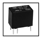
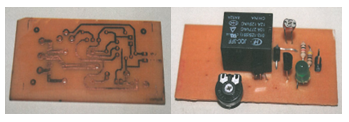
Figure 2 : Relay circuit
Figure 3 : LDR circuit
Analysis:-

The hardware circuit is design by using PCB board. To complete this design, we need to follow the step above. The first one, we need to aching the PCB board and then solder the circuit to make sure each line will be connected with each other line.

Conclusion: -
For the conclusion after we design the circuit diagram in the program software, we try on the PCB board to construct the circuit follow in the software. The software help a lot on the design of circuit, follow the PIC pin configuration and the port that we decide construct on the PCB board.

Monday 23 September 2013

WEEK 3 : FYP 2 : SELECT SOFTWARE PROGRAMMING

Title            : Find and understand about software
Objective    : To find and understand about software for this project
Content       : Ensure that software used is suitable for this project


Figure 1 : PROTEUS and MPLAB
Analysis:-
In this project, two types of software is used which is Proteus and MPLAB IDE. The language that used for this project is c language. Proteus is used to design circuit for hardware while MPLAB is used to create a program.

Conclusion:-
As the conclusion, I got a lot of knowledge how to used this software. I also learn about how this software can be link with the hardware.

Monday 16 September 2013

WEEK 2 : FYP 2 : FIND COMPONENT

Title           : Find & understand component used
Objective   : To find and understand all component that used
Content      : 1) Ensure that all component for this project was purchased
                    2) Understand function of each component

Figure 1 : LDR sensor
Figure 2 : PIC 16F877A
Figure 3 : Relay
Analysis
The main component that used for this project are light dependent resistor (LDR) sensor, relay and PIC16F877A microcontroller.
Conclusion:
As the conclusion, the objective of this project is achieved. All the component for this project was purchased. Then, I got and learn more information about the component for this project.

Monday 9 September 2013

WEEK 1 : FYP 2 : RESEARCH ON PROJECT

Proceed to the next level from fyp semester 1, I do some research from the work flow to do some confirmation what type of circuit have to run my project. The circuit that will design depends on the flowchart of my project. So, after that i need to making the program code for the normal mode and flexible mode.

Figure 1 : Flow of final project
                                                                      
                                      
As the conclusion, it is very important to understand the circuit, classified the type and its function all of the circuit to make sure there is no problem occur in the future in the part of the combination the circuit and the programming development.