Saturday 21 December 2013

WEEK 14 : FYP 2 : COMPLETE FINAL YEAR PROJECT REPORT AND PRESENTATION DAY

Title             : Complete final year project report and presentation day

Objective     : 1)To complete the report of final year project
                      2) To show and present the result final year project to assessor

Contents and procedure :

(1) Discuss with lecturer in term of final year project presentation and report
(2) Research internet what are include in final year project report.
(3) Follow guideline in fyp website about the format


Conclusion:

As for the conclusion, in order to achieve the objective of this project, the knowledge of each part of the project such as sensor,  PIC circuit, programming that using C programming as the source code of programming and microcontroller PIC16F877A as the main hardware, need to research more. This system use the subject such as microcontroller & interfacing as the source of information in order to understand the concept, theory, problem and solution of this project.

Friday 6 December 2013

WEEK 13 : FYP 2 : PREPARATION FOR FYP PRESENTATION

Title               : Preparation for Fyp presentation
Objective       : To present the Final Year Project
Content          : 1) Make sure project function
                        2) Study all technical and theoretical of project

Study on component datasheet :-

Figure 1 : LDR data sheet
Figure 2 : PIC data sheet


Analysis:


Based on this project, student should know what are learning during doing this project. It including the technical and theoretical of component/software used. For my project, I need to know how the sensor and microcontroller specification. For example, I should be know how much current, voltage and watt will produce by the component that used.

Conclusion:
Finally, student should present all of work done to assessor. The objective to show what are student had learn around 1 year doing research of project.

Monday 25 November 2013

WEEK 12 : FYP 2 : DESIGN POSTER AND SLIDE FOR FYP PRESENTATION

Title             : Make a poster and slide for the fyp presentation
Objective     : To design a poster and slide about whole project background

Content        : 1) Explain about the project
                      2) Clearly the main objective
                      3) Design the block diagram
                      4) Flow chart about the project from beginning until the end
                      5) Make a result and analysis
                      6) Conclusion about this project

Poster design :-

Figure 1 : Poster design
Slide :-

Figure 2 : Slide for presentation
Analysis:-

From the poster and slide it will describe everything about the project. The assessor can understand about the project from the poster. Block diagram can explain more clearly based on the block show. The block diagram shows the input and the output from the PIC. The conclusion is concluding about the whole project.

Conclusion :-
As the conclusion the poster and slide is the most important thing to describe about our project. When the assessor read all the data and information on the poster and slide it will give them satisfaction and just ask when they don’t know certain about the project.

Monday 18 November 2013

WEEK 11 : FYP 2 : TROUBLESHOOT ALL PART OF THIS PROJECT

Title             : Troubleshoot all part which is PIC circuit, LDR sensor circuit and relay circuit
Objective     : To make sure all the circuit is functioning
Content        : 1) Testing the functionality of PIC circuit
                      2) Testing the functionality of relay circuit
                      3) Testing the functionality of LDR sensor

Result:-

 
Figure 1 : Testing circuit

Monday 11 November 2013

WEEK 10 : FYP 2 : CONSTRUCT FLEXIBLE TRAFFIC LIGHT MODEL

Title             : Develop flexible traffic light model
Objective     : To ensure that the flexible traffic light model is built according to the draft
Content        : Construct the flexible traffic light model using plastic base

Result :-

Figure 1 : Complete model
 Analysis:-

From the picture above shows the complete model of flexible traffic light. The design is basically get from the internet based on the existing product. The wire more important because it can make short circuit, it will damage for this project. The model also small, so it is easy to carry and testing the hardware.

Conclusion :
To make some design, we must take note all this aspect such as material that will be used, their costing, product, sizing, item endurance and also their usage. If we miss some of that part, the design will not completely useful.

Monday 4 November 2013

WEEK 9 : FYP 2 : LDR CIRCUIT PROGRESS

Title           : Making and testing the light dependent resistor (LDR) sensor program
Objective   : 1) To develop coding of light dependent resistor (LDR) sensor
                   2) To ensure the coding can be run properly with the hardware
Content      : 1) Develop coding for light dependent resistor (LDR) sensor
                    2) Testing the coding that can be link with the circuit or not

Result :-

Figure 1 : LDR circuit

Analysis:-

The hardware development is suitable matches with the software; it proves when the hardware function, the coding for normal and flexible mode is functioning.
 
Conclusion:-
As a conclusion the result achieve what we expected, and the circuit is function when it matches with the software. The combination of the hardware and software is important to produce the output based on we need.

Monday 28 October 2013

WEEK 8 : FYP 2 : RELAY CIRCUIT PROGRESS

Title           : Making and testing the relay circuit and program
Objective   : 1) To develop coding of relay circuit for normal and flexible mode                            
                   2) To ensure the coding can be run properly with the hardware

Content     : 1) Develop coding for normal and flexible mode
                   2) Testing the coding that can be link with the circuit or not

Result:-

Figure 1 : Relay circuit


Analysis:-

The hardware development is suitable matches with the software; it proves when the hardware function, the coding for normal and flexible mode is functioning.
 
Conclusion:-
As a conclusion the result achieve what we expected, and the circuit is function when it matches with the software. The combination of the hardware and software is important to produce the output based on we need.

Monday 21 October 2013

WEEK 7 : FYP 2 : PIC CIRCUIT PROGRESS

Title          : Making and testing the PIC circuit and program
Objective  : 1) To develop coding of PIC circuit for normal and flexible mode                            
                  2) To ensure the coding can be run properly with the hardware

Content     :1) Develop coding for normal and flexible mode
                  2) Testing the coding that can be link with the circuit or not

Result:-


Figure 1 : PIC circuit
Analysis:-

The hardware development is suitable matches with the software; it proves when the hardware function, the coding for normal and flexible mode is functioning.
 
Conclusion:-
As a conclusion the result achieve what we expected, and the circuit is function when it matches with the software. The combination of the hardware and software is important to produce the output based on we need.

Monday 14 October 2013

WEEK 6 : FYP 2 : TEST OR TROUBLESHOOT INTERFACING CIRCUIT

Title           : Test or troubleshoot the interfacing circuit between PIC circuit with output circuit
Objective   : 1) To know the circuit function properly
                   2) To troubleshoot when the circuit have a problem

Content/Procedure:
• Burn the program into PIC circuit
• Check the program related or not with PIC circuit
• Interface the PIC circuit with output circuit
• Check again and ensure the overall circuit working as expected and is same with simulate in proteus

Analysis:-
For this project, at the PIC circuit I burn the program as directly and not use other out interface component because in software MPlab IDE have a PICkit2 software and just connected the wire from computer to PIC circuit but make sure at the PIC circuit have a pin IDC10 connector with PIC and it one of component from In Circuit Serial Programing ( ICSP ).

Conclusion:-
Circuit is working properly and knows how to burn the program into PIC, troubleshoot circuit also interfacing PIC circuit with output circuit have done. So, in this task the objective is achieved.

Monday 7 October 2013

WEEK 5 : FYP 2 : STUDY OF PROGRAMMING IN C

Title                 : Study programming of PIC microcontroller
Objective         : To ensure the PIC microcontroller is operate
Content            : Study on input (i/p) and output (o/p) pin

Result:-


Figure 1 : PIC pin configuration


Analysis:-

MPLAB sofware has been select to make the PIC microcontroller program coding for my project.  From the simulation program wrote an ASM language and compile with the MPLAB to running the program in PIC 16F877A.


Conclusion:
As a conclusion,the program that build from the MPLAB successfully match for the simulation on the circuit. The declaration on the port at PIC is easy to make a command after define the suitable port for input and output.

Monday 30 September 2013

WEEK 4 : FYP 2 : DESIGN CIRCUIT

Title                           : Design circuit for project
Objective                   : To build the circuit of this project.
Procedure/Content     : 1) Design circuit by using software
                                   2) Print the design on the transparent paper
                                   3) Stick the design with the PCB board
                                   4) Drill and solder all the component
                                   5) Test running the circuit with the program

Result:-

Figure 1 : PIC circuit


Figure 2 : Relay circuit
Figure 3 : LDR circuit
Analysis:-

The hardware circuit is design by using PCB board. To complete this design, we need to follow the step above. The first one, we need to aching the PCB board and then solder the circuit to make sure each line will be connected with each other line.

Conclusion: -
For the conclusion after we design the circuit diagram in the program software, we try on the PCB board to construct the circuit follow in the software. The software help a lot on the design of circuit, follow the PIC pin configuration and the port that we decide construct on the PCB board.

Monday 23 September 2013

WEEK 3 : FYP 2 : SELECT SOFTWARE PROGRAMMING

Title            : Find and understand about software
Objective    : To find and understand about software for this project
Content       : Ensure that software used is suitable for this project


Figure 1 : PROTEUS and MPLAB
Analysis:-
In this project, two types of software is used which is Proteus and MPLAB IDE. The language that used for this project is c language. Proteus is used to design circuit for hardware while MPLAB is used to create a program.

Conclusion:-
As the conclusion, I got a lot of knowledge how to used this software. I also learn about how this software can be link with the hardware.

Monday 16 September 2013

WEEK 2 : FYP 2 : FIND COMPONENT

Title           : Find & understand component used
Objective   : To find and understand all component that used
Content      : 1) Ensure that all component for this project was purchased
                    2) Understand function of each component

Figure 1 : LDR sensor
Figure 2 : PIC 16F877A
Figure 3 : Relay
Analysis
The main component that used for this project are light dependent resistor (LDR) sensor, relay and PIC16F877A microcontroller.
Conclusion:
As the conclusion, the objective of this project is achieved. All the component for this project was purchased. Then, I got and learn more information about the component for this project.

Monday 9 September 2013

WEEK 1 : FYP 2 : RESEARCH ON PROJECT

Proceed to the next level from fyp semester 1, I do some research from the work flow to do some confirmation what type of circuit have to run my project. The circuit that will design depends on the flowchart of my project. So, after that i need to making the program code for the normal mode and flexible mode.

Figure 1 : Flow of final project
                                                                      
                                      
As the conclusion, it is very important to understand the circuit, classified the type and its function all of the circuit to make sure there is no problem occur in the future in the part of the combination the circuit and the programming development.


Friday 22 March 2013

EXPECTED OUTCOME

Development of flexible traffic light using verilog HDL and implemented the verilog HDL using ALTERA DE2 for proof the concept in normal mode and flex mode.

FLOW CHART

NORMAL MODE


FLEX MODE


Friday 8 March 2013

LITERATURE REVIEW

Jose E.Ortiz, Robert H.Klenke, Simple Traffic Light Controller: A Digital Systems Design Project.Electrical And Computer Engineering Department Virginia Commonwealth University

  • This project required students to develop a state machine based controller for traffic signals at a four-way intersection. The intersection has two travel lanes in each direction; north, south, east and west. In addition, each direction has a dedicated left turn lane. Each lane contains a sensor to indicate if a car waiting at a red light. Travel lanes also contain additional sensors to indicate if cars are approaching the intersection.


Boon Kiat Koay, Maryam Mohd Isa, Traffic Light System Design On FPGA. Proceeding of 2009 IEEE Student Conference On Research And Development, 16 – 18 November 2009, UPM Serdang

  • This project design of a low cost performance traffic light system. This type of traffic light is suitable for town and small city where sophisticated traffic light system is too costly. Written in verilog on Quartus II software and implemented on DE2 FPGA Board.

Friday 1 March 2013

AIM N OBJECTIVES

  • To develop flexible traffic light controller
  • To develop verilog HDL for flexible traffic light systems
  • To implement the verilog HDL using ALTERA DE2 for proof the concept

Friday 22 February 2013

PROBLEM STATEMENT


Before, the traffic light using timer without sensor is an ineffective traffic light. Usually the traffic light systems in Malaysia use an inductive loop to detect a car when arrives at an intersection or to control the length of the light. Based on the research, this system was invented only to smooth traffic flow at the junction. The effects of heavy traffic congestion can impact in personal life, career, future, and safety. Flexible traffic light one of the system that can avoid traffic congestion and accident.  


Friday 15 February 2013

INTRODUCTION

The traffic light, also known as traffic signal, stop light, traffic lamp, stop-and-go lights, robot or semaphore, is a signalling device positioned at aroad intersections. It use as the road signal for directing vehicular traffic by means of coloured lights. In most countries, the sequence is red (stop), green (go), yellow (prepare to stop). In some cases, traffic signals also indicate to drivers when they may make a turn.

     These signals may be operated manually or by a simple timer which allows traffic to flow on one roadway for a fixed period of time, and then on the other roadway for another fixed period of time before repeating the cycle. Other signals may be operated by sophisticated electronic controllers that sense the time of day and flow of traffic to continually adjust the sequence of operation of the signals.

    A modern traffic signal system consists of three basic subsystems: the signal lights in their housing, the supporting arms or poles, and the electric controller. The signal lights and housing are known as the signal light stack. A single stack usually consists of three lights : a green light on the bottom to indicate the traffic may proceeds, a yellow light in the middle to warn traffic to slow and prepare to stop, and a red light on the top to indicate the traffic must stop.

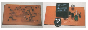
    Traffic light system controller gives sign of direction and warning, or it establishes a set of rule and instructions to road users to follow to avoid any road accident. Flexible traffic light controller is needed 
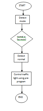
for maximizing the flow rate of vehicle at the junction. Development of flexible traffic light using verilog HDL is in two mode: normal mode that control the green light timer using switch, flex mode is using line sensor if sensor detect car on lane green timer use the value from switch and turn to red light  if detect no car.