Monday, 4 November 2013

WEEK 9 : FYP 2 : LDR CIRCUIT PROGRESS

Title           : Making and testing the light dependent resistor (LDR) sensor program
Objective   : 1) To develop coding of light dependent resistor (LDR) sensor
                   2) To ensure the coding can be run properly with the hardware
Content      : 1) Develop coding for light dependent resistor (LDR) sensor
                    2) Testing the coding that can be link with the circuit or not

Result :-

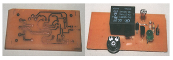
Figure 1 : LDR circuit

Analysis:-

The hardware development is suitable matches with the software; it proves when the hardware function, the coding for normal and flexible mode is functioning.
 
Conclusion:-
As a conclusion the result achieve what we expected, and the circuit is function when it matches with the software. The combination of the hardware and software is important to produce the output based on we need.

Monday, 28 October 2013

WEEK 8 : FYP 2 : RELAY CIRCUIT PROGRESS

Title           : Making and testing the relay circuit and program
Objective   : 1) To develop coding of relay circuit for normal and flexible mode                            
                   2) To ensure the coding can be run properly with the hardware

Content     : 1) Develop coding for normal and flexible mode
                   2) Testing the coding that can be link with the circuit or not

Result:-

Figure 1 : Relay circuit


Analysis:-

The hardware development is suitable matches with the software; it proves when the hardware function, the coding for normal and flexible mode is functioning.
 
Conclusion:-
As a conclusion the result achieve what we expected, and the circuit is function when it matches with the software. The combination of the hardware and software is important to produce the output based on we need.

Monday, 21 October 2013

WEEK 7 : FYP 2 : PIC CIRCUIT PROGRESS

Title          : Making and testing the PIC circuit and program
Objective  : 1) To develop coding of PIC circuit for normal and flexible mode                            
                  2) To ensure the coding can be run properly with the hardware

Content     :1) Develop coding for normal and flexible mode
                  2) Testing the coding that can be link with the circuit or not

Result:-


Figure 1 : PIC circuit
Analysis:-

The hardware development is suitable matches with the software; it proves when the hardware function, the coding for normal and flexible mode is functioning.
 
Conclusion:-
As a conclusion the result achieve what we expected, and the circuit is function when it matches with the software. The combination of the hardware and software is important to produce the output based on we need.

Monday, 14 October 2013

WEEK 6 : FYP 2 : TEST OR TROUBLESHOOT INTERFACING CIRCUIT

Title           : Test or troubleshoot the interfacing circuit between PIC circuit with output circuit
Objective   : 1) To know the circuit function properly
                   2) To troubleshoot when the circuit have a problem

Content/Procedure:
• Burn the program into PIC circuit
• Check the program related or not with PIC circuit
• Interface the PIC circuit with output circuit
• Check again and ensure the overall circuit working as expected and is same with simulate in proteus

Analysis:-
For this project, at the PIC circuit I burn the program as directly and not use other out interface component because in software MPlab IDE have a PICkit2 software and just connected the wire from computer to PIC circuit but make sure at the PIC circuit have a pin IDC10 connector with PIC and it one of component from In Circuit Serial Programing ( ICSP ).

Conclusion:-
Circuit is working properly and knows how to burn the program into PIC, troubleshoot circuit also interfacing PIC circuit with output circuit have done. So, in this task the objective is achieved.

Monday, 7 October 2013

WEEK 5 : FYP 2 : STUDY OF PROGRAMMING IN C

Title                 : Study programming of PIC microcontroller
Objective         : To ensure the PIC microcontroller is operate
Content            : Study on input (i/p) and output (o/p) pin

Result:-


Figure 1 : PIC pin configuration


Analysis:-

MPLAB sofware has been select to make the PIC microcontroller program coding for my project.  From the simulation program wrote an ASM language and compile with the MPLAB to running the program in PIC 16F877A.


Conclusion:
As a conclusion,the program that build from the MPLAB successfully match for the simulation on the circuit. The declaration on the port at PIC is easy to make a command after define the suitable port for input and output.

Monday, 30 September 2013

WEEK 4 : FYP 2 : DESIGN CIRCUIT

Title                           : Design circuit for project
Objective                   : To build the circuit of this project.
Procedure/Content     : 1) Design circuit by using software
                                   2) Print the design on the transparent paper
                                   3) Stick the design with the PCB board
                                   4) Drill and solder all the component
                                   5) Test running the circuit with the program

Result:-

Figure 1 : PIC circuit


Figure 2 : Relay circuit
Figure 3 : LDR circuit
Analysis:-

The hardware circuit is design by using PCB board. To complete this design, we need to follow the step above. The first one, we need to aching the PCB board and then solder the circuit to make sure each line will be connected with each other line.

Conclusion: -
For the conclusion after we design the circuit diagram in the program software, we try on the PCB board to construct the circuit follow in the software. The software help a lot on the design of circuit, follow the PIC pin configuration and the port that we decide construct on the PCB board.

Monday, 23 September 2013

WEEK 3 : FYP 2 : SELECT SOFTWARE PROGRAMMING

Title            : Find and understand about software
Objective    : To find and understand about software for this project
Content       : Ensure that software used is suitable for this project


Figure 1 : PROTEUS and MPLAB
Analysis:-
In this project, two types of software is used which is Proteus and MPLAB IDE. The language that used for this project is c language. Proteus is used to design circuit for hardware while MPLAB is used to create a program.

Conclusion:-
As the conclusion, I got a lot of knowledge how to used this software. I also learn about how this software can be link with the hardware.